UML diagrams best scenarios [Real Examples]
As a software house in Tenth of Ramadan city, we receive requests for technical consultation from time to time regarding business process/automation improvements. In this post, we will explore various UML modelling implementations through real life projects.

1- UML in action: SFD project
One of our current clients is the SFD – Social Fund for Development – which is a government organization specialized in funding small-medium business projects, where applicants from all over Egypt apply for projects’ funding in one of the SFD’s 32 offices and it is the SFD role to study the applications and decide whether – or not – to fund the project. This will be my first example.
Our first role with the SFD is to help them improve and speedup the application cycle from start to end. In this post, I would like to share some shareable information as I think it will help those who would like to see models and diagrams in action.
A) Behavioral Modelling:
Sequence Diagram
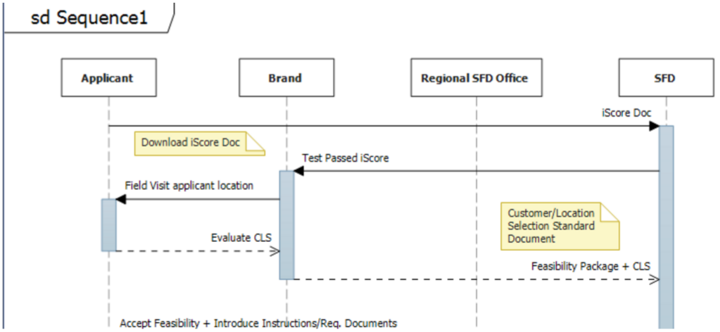
To improve the application cycle, it is important to understand the current system first as this will allow us to avoid the shortcomings and defects. In order to achieve this, behavioral model can be the best choice. I choose to use Sequence Diagram to model the core process sequence after interviewing the responsible senior executive. As explained by Donald Bell from IBM, the diagram purpose is that ‘organization’s business staff can find sequence diagrams useful to communicate how the business currently works by showing how various business objects interact’. In figure 1, I’ve shared snippet of the current Sequence Diagram.

Fig. 1 – SFD Sequence Diagram
As can be determined from Fig.1, the Sequence diagram has two main characteristics:
1- The Sequence diagram is one-direction way: Sequence diagram explains the flow of processes considering the everything is working in the right direction, simplifying the first stage of analysis.
2- It has incoming and outgoing messages: Each Actor can send inquiries or receive inputs in a form of Request-Response.
B) Use Case Diagram
To wrap up the user activities a Use Case diagram can be added in order to summarize each actor and its use cases.
C) Developing the SFD Structural Model:
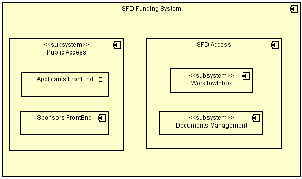
The SFD model is still under development, it is to be extended and elaborated as we increase our understanding of the system that is to be built. But according to this early stage of analysis, I propose the model architecture in Fig 2 designed using the free Astah community edition.

Fig. 2 – SFD Funding Component diagram
D) Ending up with an Architectural Model
The Architectural model is one of the richest models, as it provides both structural and behavioral characteristics of the system, yet it is possible to model the system architecturally in the further investigation of the current system.
2- Sales Analysis Project
UML Behavioural model is also used with Sales analysis for a any business. Use Cases can be used to identify the behavior of different consumers’ segments/types with different products. Consumers can then be segmented according to their geographical location, race, age or gender to better understand the behaviour for each group. Each group can be identified in Use Case Model as actors within multiple Use Case diagrams that shaped the overall behaviour.
Analyzing Consumer behavior is not a new term, as a matter of fact it is as along as the marketing science; this is because it studies what satisfies customers by analyzing what, where, when and how consumers buy. And also, Marketers can better predict how consumers will respond to marketing strategies. (Brawn, 1996)
Amazon, for example, uses this to show a user who visits a particular book – the module’s textbook as happened in my case – what else in common other users who bought this book did bought as well.
A business can eventually have a model that contains the following:
a- Consumer Behavior Use Cases.
b- Component Diagrams showing the items categorization within the store, which will be used with the customer behavior to better analyse the sales performance and the mutually exclusive sold products/services.
3- Another UML example in Call Centers Project
Although my business doesn’t have a dedicated call center, our network technician – previously worked as a call center agent for an internet providing company – had told us that the company he used to work for trains the new customer support agents to respond to customers in a form of Activity diagram, while each question/response triggers another till the issue is resolved or is escalated. To model all issues well, they also have a component diagram that models the network components for the subscribers.
For call centers, the following can compose the model:
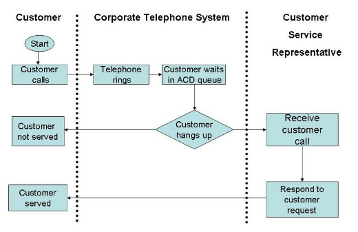
1- Customer Care Activity Diagram: Fig 3 is a diagram from the article ‘Service Time Flowchart’ by Gordon M. Clark shows a high level activity diagram for the Customer-Customer Service Representative interaction.
2- Component Diagram to illustrate standard network components and common issues per component.

Fig. 3 – Customer care activity diagram
Conclusion
In my opinion, I believe that using diagrams from multiple UML models to for a hybrid model for a system will enrich the modelling process and will reflect more views and perspectives rather than using single modelling methodology. For those who are looking for a great reference for UML, I recommend reading the book (Object-Oriented Systems Analysis and Design using UML) by Bennet, McRobb and Farmer.
Useful articles
If you liked this article, you may also read this interesting article about Sequence Diagramming from Creately team.

No Comments